-
Manufacturers
Manufacturers


What Types Of Digital Encoders Are Used In CNC Machine Controls?
When it comes to digital encoders commonly used in CNC machine controls, the options are rotary encoders, angle encoders, and linear encoders. However, in terms of accuracy, it can be further classified as absolute and incremental encoders. Moreover, in terms of how the feedback is recognized and relayed, it can be differentiated even further between optical and magnetic encoders. In this blog, Walker Machinery, a major distributor of digital encoders and DRO systems in Milton, Ontario, explores these encoders and their applications in detail.
What Encoders Are Best Suited For CNC Machine Controls?
The main purpose of all digital encoders here is to bridge the gap between the CNC control and the respective motor by offering accurate feedback. With this basic definition, it can be further differentiated as:
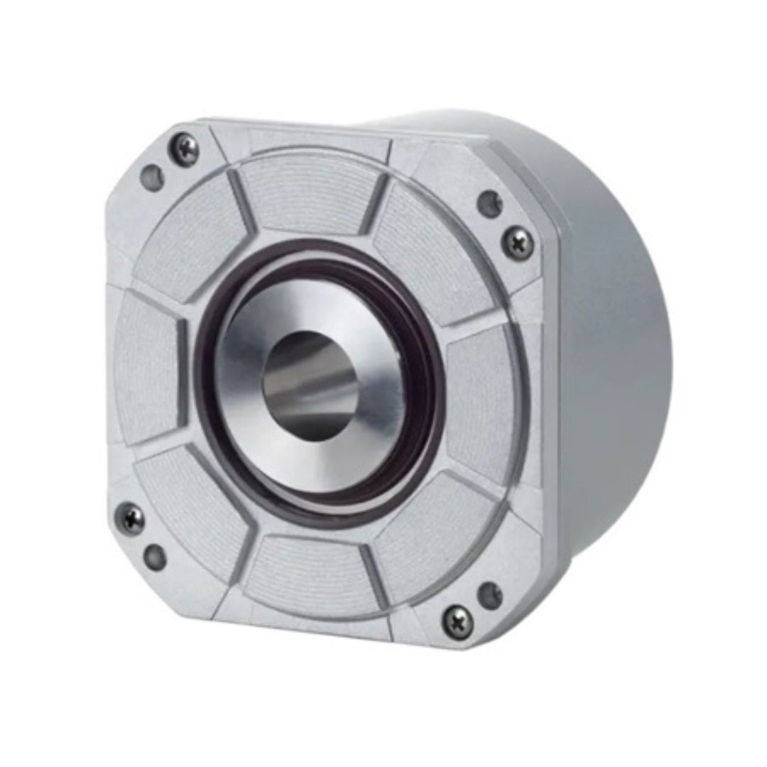
Angle Encoders
Angle encoders are a highly precise feedback tool that measures the relationship between two rotating parts in a CNC machine. The accuracy of this feedback is higher than +/- 10 arcseconds and can be as high as +/- 0.4 arcseconds in some cases. Since the level of accuracy and precision is unmatched, angle encoders are often used in multi-axis CNC machining centers, specifically in rotary tables and swivel heads. This is because angle encoders can provide for both simultaneous and independent movement.
Rotary Encoders
Rotary encoders are a more standard feedback device, which are fairly accurate, but not as accurate as angle encoders. However, they still have an accuracy above +/- 10 arcseconds, making them a staple in many CNC applications. Instead of positioning, rotary encoders are often used for monitoring and controlling speed. In machine tools, these encoders are often deployed to measure the RPM of the spindle, which helps determine key factors such as speed of feed, tool wear, and energy consumption during operation.
Linear Encoders
Linear encoders are fairly straightforward in operation. They measure the distance in a straight line in a machine tool or CNC machine. However, they play a key role in machines using servo motors, where angle and rotary encoders are not suitable for specific tasks. Most 3-axis machine centers, such as lathes, use servo motors to move the workpiece in a linear fashion along the X, Y, and Z-axis.
The servo motor is used here to move a screw-like shaft, which is connected to the table and directs its movement. A digital encoder is meant to measure the speed and distance of this movement. But, with prolonged use, factors such as reversal errors and axial drift come into play. Since angle and rotary encoders cannot account for these factors, a linear encoder is used in such cases. Moreover, considering the extreme environment of operation, most linear encoders are sealed to protect the scale and sensitive equipment from heat, contaminants, and excessive vibration.
How Accuracy Is Measured In Machine Tools?
How do digital encoders recognize parameters such as position and speed and relay them to the controller? For this, they use two scales or discs. One is stationary and the other moves with the tool. The relationship between them is used to convey speed and positioning. The variations are recognized by markings or graduations. Based on this, there are two primary distinctions: absolute encoder and incremental encoder.
Absolute Encoders
Absolute encoders comprise scales or wheels with distinct and nuanced markings on them. The scanning mechanism of the encoder uses this to measure the speed and position of a particular task. The main advantage of an absolute encoder is that they do not have or require a reference point. When the machine starts and stops, the controller acquires the specific positioning instantly. Therefore, there is no need to zero out the encoder before each operation.
Incremental Encoders
Incremental encoders are similar in operation to absolute encoders. However, the main difference is that instead of smaller markings, this encoder has more uniform markings stating relative position and not the absolute position. Therefore, after each operation, when the machine is restarted, a zero point or reference point has to be established.
How Encoder Markings Are Recognized In Machine Tools?
The markings on the disc or scale of a digital encoder can be recognized in two fundamental ways: optically or magnetically.
Optical Encoders
In the case of optical encoders, the way the light interacts with the markings on the encoder helps determine the accurate speed and position of a movement.
Magnetic Encoders
In the case of magnetic encoders, there are magnetic patterns instead of light, and based on the change in magnetic resistance, the feedback is sent to the controller to relay movement and speed.
Conclusion
In closing, the main types of encoders used in CNC machine controls are angle, rotary and linear encoders. However, on the basis of accuracy, it can be sub-classified as absolute or incremental encoders. Lastly, based on how the readings on the encoders are recognized, it can be differentiated between optical and magnetic encoders. That being said, all variations and combinations are used in one form or another in CNC machining. The selection depends on the desired accuracy, cost, compatibility and environmental factors.
To learn more about digital encoders and DRO systems, contact us at Walker Machinery today. As one of the leading distributors of linear encoders, rotary encoders and more, we also offer high-quality digital readout systems and related accessories. With decades of experience in this field, we proudly serve a wide variety of industries and esteemed clients. For more information, contact us at 905-876-0890 today.
FAQs:
How do digital encoders impact CNC machining?
Digital encoders affect every key factor in CNC machining, such as accuracy, speed, safety, setup, usability and cost.
What are the key applications of digital encoders in robotics?
Key applications of digital encoders in robotics include robotic arm joint positioning, agv navigation and steering, sensor orientation and end-effector precision.